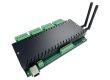

What happens when a 16-channel relay controller gets a sci-fi dashboard?
The KinCony CO16 Cyber Show turns an ESP32-S3 controller into a miniature control console, combining animated radar graphics, rotating energy rings, and a colorful spectrum display with real relay sequences.
This ESP32 relay board demo runs as a standalone Arduino sketch. Once uploaded, it automatically plays a 32-second show using the CO16’s built-in ST7789 color display and 16 relay channels. No external sensors, Ethernet connection, or SD card are needed.
We have tested the sketch on a physical KinCony CO16 board and confirmed that it runs successfully.
Five Scenes, One ESP32-S3 Controller
The Cyber Show moves through five scenes automatically. Each scene pairs a different display animation with a relay pattern.
| Scene | Display Animation | Relay Pattern |
|---|---|---|
| System Boot | KinCony branding and an animated progress bar | Sequential channel scan |
| Relay Radar | Rotating radar sweep with 16 highlighted nodes | One channel at a time |
| Energy Core | Counter-rotating rings and animated energy bars | Two channels moving inward and outward |
| Beat Matrix | Cyan and magenta spectrum-style bars | Alternating groups of four relays |
| One Brain | “16 CHANNELS. ONE BRAIN.” closing screen | Reverse scan followed by all relays off |
The complete sequence repeats, making it easy to watch, demonstrate, or record.


Relay Radar: Watch the Channels Move
The radar screen places 16 nodes around a circular display. As the relay sequence advances, the corresponding node lights up.
Numbered tiles along the bottom of the screen also show the output commands, helping viewers connect what they see on the LCD with the board’s relay activity.
These graphics represent commands sent to the relay expander. They are not independent measurements of the physical relay contacts.
Energy Core: Two Waves Meet in the Middle
In the Energy Core scene, cyan and magenta rings rotate in opposite directions around a central “16.”
Meanwhile, two active relay channels travel from opposite ends toward the center and back again. The combination gives a simple relay sequence a distinctive control-room appearance.
Beat Matrix: A Visual Rhythm
Beat Matrix adds animated spectrum-style bars and a fixed 120 BPM visual beat indicator. Four relay groups alternate with off intervals to create a rhythmic sequence.
The spectrum is generated mathematically. It does not use a microphone, analyze audio, or automatically synchronize with music.
Hardware Used in This Arduino Project
The demo uses the KinCony CO16, an ESP32-S3 controller with an integrated color display and multiple onboard I/O interfaces.
For this project, the main components are:
| Component | Purpose |
|---|---|
| ESP32-S3 | Runs the animation and relay sequence |
| ST7789 TFT display | Shows the 320 × 240 landscape interface |
| PCF8575 I/O expander | Controls the 16 relay outputs through I²C |
| Onboard relay indicators | Make the channel sequence visible |
Everything needed for the visual demonstration is already on the controller. You do not need to wire individual LEDs to a breadboard or connect an external display.
For the board’s complete specifications and interfaces, visit the KinCony CO16 ESP32-S3 smart controller product page.
How to Run the CO16 Cyber Show
1. Prepare the Board
You will need:
- A KinCony CO16 with PCF8575 relay outputs.
- A suitable power supply for the controller.
- A USB data cable.
- A computer with Arduino IDE and ESP32 board support installed.
- The
CO16_Cyber_Show.inosketch.
Keep external loads disconnected from the relay terminals during this demonstration. The LCD and onboard indicators provide the visual effects without switching connected equipment.
2. Install the Required Libraries
In Arduino IDE’s Library Manager, install:
- Adafruit GFX Library
- Adafruit BusIO, if prompted as a dependency.
The sketch includes the CO16-specific ST7789 driver and writes directly to the PCF8575 over I²C. It does not require a separate PCF8575 library or the Adafruit ST7789 library.
3. Upload the Arduino Sketch
Open CO16_Cyber_Show.ino in Arduino IDE. You can also download firmware BIN file by ESP32 Download Tool directly without arduino IDE.
Select ESP32S3 Dev Module, choose the correct USB port, and retain the board settings that work with your CO16 factory test sketch.
Compile and upload the program. Once the controller restarts, the automatic show begins.
Uploading this demo replaces the application firmware currently running on the ESP32-S3. Keep your normal firmware and configuration available if you plan to return the board to an automation installation.
4. Watch the Automatic Sequence
The default show runs through:
System Boot → Relay Radar → Energy Core → Beat Matrix → One Brain
The sequence takes approximately 32 seconds and then starts again. After programming, the demo does not require a connected computer to continue running.
Control the Demo from Arduino Serial Monitor
For presentations or close-up video recording, you can select individual scenes through Serial Monitor.
Set the baud rate to 115200 and send one of the following characters:
| Command | Action |
|---|---|
0 |
Restart the automatic show |
1 |
Select System Boot |
2 |
Select Relay Radar |
3 |
Select Energy Core |
4 |
Select Beat Matrix |
5 |
Select One Brain |
p |
Pause or resume; pausing switches the relays off |
x |
Disable relay motion and keep the screen animation running |
e |
Enable relay motion again |
r |
Restart the automatic show |
For example, send 2 to keep the radar scene selected while recording. Send 0 to return to the complete sequence.
Use x when you want to demonstrate the graphics without repeatedly operating the mechanical relays.
How the Display and Relay Effects Work
The sketch handles display rendering and relay updates on separate schedules.
Graphics are first drawn into a 320 × 240 RGB565 frame buffer in memory. The completed frame is then transferred to the ST7789 through the ESP32-S3’s SPI3 interface in smaller chunks. This reduces the visible intermediate drawing steps that can occur when individual shapes are drawn directly on the screen.
Relay commands are updated no more frequently than once every 250 milliseconds during the automatic sequence. This lets the display animate independently of the slower mechanical outputs.
A single two-byte I²C write updates all 16 PCF8575 output bits. The program uses the CO16’s active-low relay logic:
- LOW: relay on.
- HIGH: relay off.
The relevant connections are:
| Function | CO16 Connection |
|---|---|
| I²C SDA | GPIO8 |
| I²C SCL | GPIO18 |
| PCF8575 relay address | 0x22 |
| TFT clock | GPIO11 |
| TFT MOSI | GPIO10 |
| TFT MISO / shared SPI bus | GPIO12 |
| TFT chip select | GPIO4 |
| TFT data/command | GPIO0 |
| TFT reset | GPIO5 |
| TFT backlight | GPIO40 |
This is a focused visual demo. It does not perform the CO16’s full factory test, read analog sensors, or run networking services.
Customize the Arduino Demo
The sketch is a starting point for your own ESP32 display and relay projects.
You can modify the scene titles, colors, radar graphics, relay patterns, and closing message. The code uses English comments to make the main sections easier to follow.
Useful settings include:
FRAME_MS: the target interval between rendered frames.RELAY_STEP_MS: the relay sequence step interval.SCENE_NAMES: the labels displayed at the top of the screen.patternFor(): the relay pattern used by each scene.
Keep the characteristics of mechanical relays in mind when modifying the sequence. Faster switching is not necessary for a strong visual effect; much of the movement can come from the display animation.
For a more practical follow-up project, the same interface ideas could be adapted to show digital inputs, sensor readings, or application status. That would require adding the appropriate input-reading and control logic.
Frequently Asked Questions
Does the demo need Wi-Fi or an internet connection?
No. The animation and relay sequences run locally on the ESP32-S3. No network connection is required.
Do I need external lights or sensors?
No. You can run the demonstration using the CO16’s built-in display, relays, and onboard indicators.
Is the spectrum animation responding to music?
No. It is a synthetic animation with a fixed visual beat. The sketch does not perform audio sampling or beat detection.
Can I run the display without operating the relays?
Yes. Send x through Serial Monitor to disable relay motion while the screen continues animating. Send e to enable it again.
Does this sketch work on every ESP32 relay board?
No. It is configured for the CO16’s ESP32-S3, ST7789 display, pin assignments, and PCF8575 relay expander. Other boards may need changes to the display driver, wiring definitions, and output-control code.
Is this intended for continuous relay cycling?
No. It is designed for short demonstrations, learning, and filming. Use screen-only mode for extended display demonstrations to avoid unnecessary mechanical relay operations.
Build Your Own CO16 Project
The Cyber Show demonstrates how a small embedded display can make multi-channel control easier to see and more engaging to explore.
Use it as a hands-on Arduino project, a workshop demonstration, or a starting point for your own controller interface.
Explore the KinCony CO16 hardware and specifications, visit the KinCony community forum for technical discussions, and follow the KinCony YouTube channel for more controller demonstrations.
16 channels. One brain. Built with KinCony.