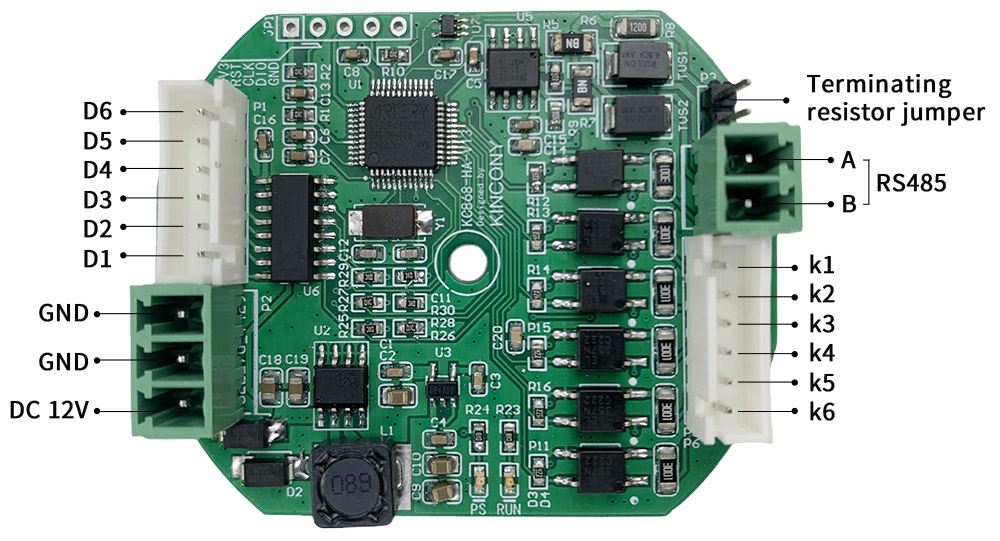
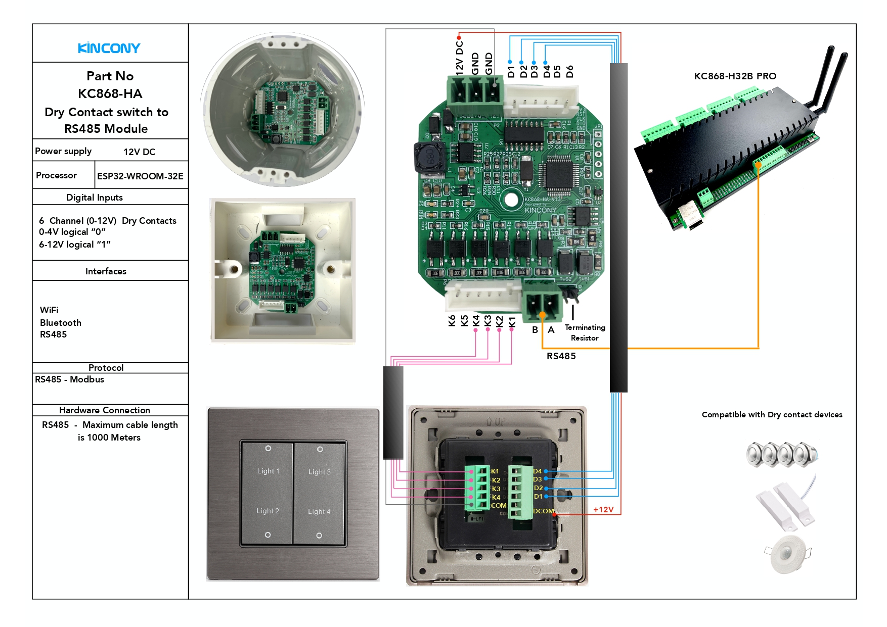
Hardware diagram:
How to config:
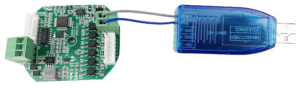
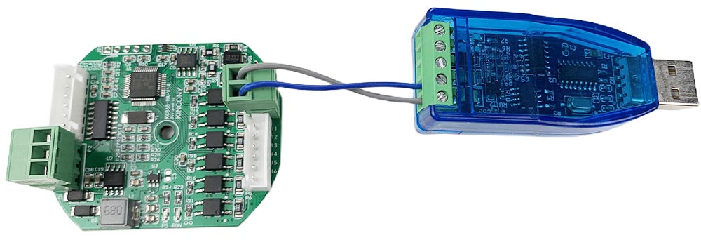
a. Use USB-RS485 adapter connect to KC868-HA.

b. download KC868-HA config tool and open it
Chose your USB Serial port, baud is “9600”, parity: None click “OPEN” button.
Target Relay Controller Addr: it’s your relay controller’s RS485 address, such as we use KC868-H32B Pro or KC868-A series board’s RS485 setting add is 1. This can see in your KinCony relay controller’s ethernet network setting webpage:
In KC868-H32B Pro setting webpage, RS485 Type set to “Special Slave” option.

“protocol” set to “MODBUS-HA” and “baud” set to 9600 in KC868-A series board config setting webpage.
Switch Adapter Addr: this is adapter board own address, you can set from 10—99, just every board set to a different address.
SW1—SW6 that is input1—6 on adapter board. SW1—SW6 means MAX support 6 buttons by one adapter board. You can set SWx type for “Latch” or “Momentary” or “EdgeEvent”, “BindOutput” for control which relay.
Fox example:
If you have two different type of switch panel. You need to prepare two adapter board.
Set adapter board-A “Switch Adapter Addr”=10
If you want SW1—SW6 use by old traditional switch panel for relay1-6. So you can connect SW1—SW6 to your switch panel’s K1–K6. Type chose “Latch”, SW1 output “1”, SW2 output “2”, SW3 output “3”…….. SW6 output “6”.
Click “Apply To” button, then click “SaveFlash” button, so that the command will saved to adapter board.

Set adapter board-B “Switch Adapter Addr”=11
If you want SW1—SW6 use by momentary switch panel for relay7-13. So you can connect SW1—SW6 to your switch panel’s K1–K6. Type chose “Momentary”, SW1 output “7”, SW2 output “8”, SW3 output “9”…….. SW6 output “13”.
Click “Apply To” button, then click “SaveFlash” button, so that the command will saved to adapter board.
EdgeEvent options:
EdgeEvent mode: you can define every button’s “RisingEdge” and “FallingEdge” for “4 different actions”.
RisingEdge: press download button
FallingEdge: release button
4 different actions code:
NoDef: do nothing
EvtON: ON
EvtOFF: OFF
EvtTog: TOGGLE
for exmaple:
this setting photo means:
relay board address is “1”, KC868-HA adapter address is “10”.
button1 pressed, TOGGLE relay1, released TOGGLE relay1 (usually use for old switch panel).
button2 pressed, TOGGLE relay2, released TOGGLE relay2, released do nothing (usually use for momentary switch panel)
button3 pressed Turn ON relay3, released Turn OFF relay1 (usually work as a binary sensor integrate to home assistant or work as a PUSH button)
button4 pressed do nothing, released TOGGLE relay4
button5 pressed Turn ON relay5, released do nothing (button always use for Turn ON device)
button6 pressed Turn OFF relay6, released do nothing (button always use for Turn OFF device)
this setting photo means:
relay board address is “1”, KC868-HA adapter address is “10”.
button1 work with relay7 which relay board address is “1”
button2 work with relay8 which relay board address is “1”
button3 work with relay9 which relay board address is “1”
button4 work with relay10 which relay board address is “1”
button5 work with relay11 which relay board address is “1”
button6 work with relay12 which relay board address is “1”
this setting photo means:
relay board address is “1”, KC868-HA adapter address is “12”.
button1 work with relay123 which relay board address is “1”
button2 work with relay124 which relay board address is “1”
button3 work with relay125 which relay board address is “1”
button4 work with relay126 which relay board address is “1”
button5 work with relay127 which relay board address is “1”
button6 work with relay128 which relay board address is “1”
how to use relay state feedback for switch panel’s LEDs:
You can use any 1-6 key switch panel.
If momentary switch panel (have LEDs), if want feedback LED indicator for state:
connect D1-D6 with switch panel’s LED D1-D6, panel have connect to +12v. Because when D1–D6 have GND then switch panel’s LED will be ON.
“ReadOnce” button: read setting from adapter board.
“RstFactory” button: will reset “Target Relay Controller Addr” to “1” , “Switch Adapter Addr” to “10”, SW1->Relay1, SW2->Relay2,SW3->Relay3,SW4->Relay4,SW5->Relay5,SW6->Relay6, “Type” to “Latch”.